This article is out of order with the planned series on my garage remodel and subsequent installation of pneumatic systems and CNC mill. I promise I’ll get back on that, but this was posted at the Saunders Machine Works forum and I might as well post it here as well so you can see more of the photos & video I took along the way.
Problem: I put Gladiator Geartrack slat wall panels around my garage to help get things up off the floor without making holes in the walls. The wall panels, hooks and shelf modules are a bit pricey but occasionally they go on sale, and they make it easy to organize things, and more importantly, re-organize things when you need to rejigger things to make it all fit.
But some things just don’t work. Bar clamps are an example. If I purchased hooks for each clamp I own, I’d be out $150-200 at the very least, and it would use the space inefficiently. Now I could go and lag some inexpensive pieces of pine or maple into the studs in the walls and make a clamp rack in the corner of the garage where I plan to put them. And I probably won’t move them once I’ve done it. But the slat wall makes moving stuff around easy, so as the garage gets revised (which has been continuous), rearranging things to fit the space available will be necessary.
So I needed some sort of bracket that would allow me to screw things into it, then hang it on the slat wall.
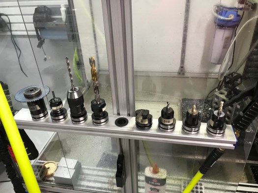
I use a lot of 80/20 extrusions around my shop. My Tormach enclosure is made from the 10 series stuff. My TTS tool racks (below) are made from 1020 extrusions and some cheap desk grommets from Amazon. So I use 1/4-20 screws all over the place since they are compatible with this type of extrusion. And as I add to the slat wall I’ll be using it for hanging air regulators and oilers and the like as well as I expand that system. So some sort of matrix of 1/4-20 screw holes similar to a fixture plate made sense.
A motley collection of tool holders if I ever saw one. Yes, that’s a TTS collet holder below.
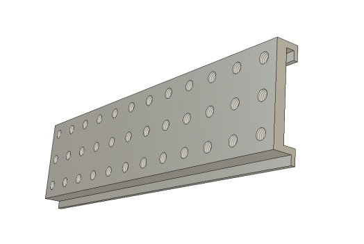
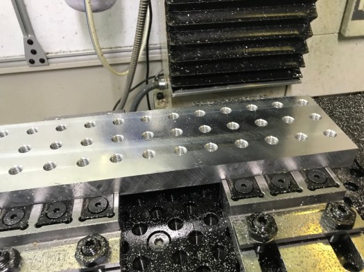
The first picture (below) is the F360 model of the matrix bracket – 12×3 7/16-14 screw holes on 1.125 spacing on center. Why 1.25″? Because my miter saw has a 1/8″ kerf and I planned to cut this up into 1″ wide pieces. (I’m reconsidering this spacing to make it more 80/20 10-series friendly, but that means saw cuts result in a <1″ part, so it’s up in the air at the moment) The 7/16-14 holes support use of a 1/4-20 threaded insert, so making the threads stronger and more durable becomes straightforward, but I can still use a 7/16 screw if that makes sense.
Picture 1: Fusion 360 CAD model
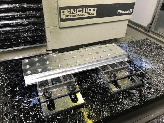
The next problem was work holding. I have a pair of GMT 6″ vises, but the blank is a bit over 14×3″ and the part is perched on top. Moreover, since I’m near the work envelope limits of my PCNC 1100, and I had a drilling operation with a large Jacobs chuck, supporting the blank in a conventional vise didn’t seem like that good an idea.
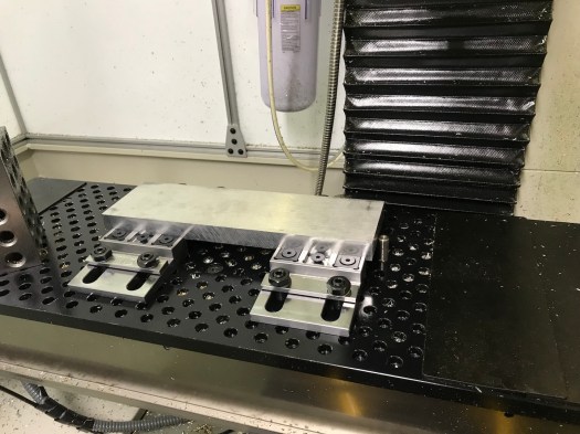
In February of 2018, I attended Saunders Machine Works’ Workholding and Fixturing class. John had already introduced his line of Mod Vises, which were interesting because a pair of mod vises would allow me to get the workpiece down near the fixture plate, leaving more room for the Jacobs chuck, and making everything a lot easier to see. Well almost (tale of woe to follow). You can see what I did in Picture 2.
Picture 2: Blank in SMW Mod Vises w/ alignment pin
Let me preface the next part of this story by pointing out that (a) I’m an electrical engineer and (b) I generally assume I’m an idiot on anything outside my specialty, so I have to learn, usually the hard way. I have a nice collection of Haimer tips and busted end mills (and one thread mill) as a evidence of this school-of-hard-knocks approach.
Making the field of screw holes was almost old hat (picture 3). I’ve used thread mills before and the only real problem was figuring out why my 7/16-14 screw threads did not accommodate 1/4-20 threaded inserts. To make a 7/16-14 thread, you first start with a U size drill, then thread it with an offset of 0.0802 and a 0.300″ diameter thread mill. And those of you who have worked with threaded inserts will immediately realize my error. If I read the spec for the insert, it requires an X diameter drill (0.397) because the insert does not have full-depth threads on it. Every hole, therefore, was wrong. I was able to fix this with my trusty 0.5 x 1/4″ LC VF stub end mill and milling out each hole to a minimum diameter of 0.397. Voilà! The inserts fit perfectly. If only that was the end of the tale…
Picture 3: Threadmilling is easy… If you know what you’re trying to do, that is.
So you practiced machinists will see almost immediately that when I set the CAM to hog out the flange on the bottom edge of my part on one side, held in place with Carr-Lane Tiny Vises and on the back side by steel clamping bars that came with the fixed jaw of the SMW Mod Vises. Add in a 1/2″ LC Variable Flute End Milland a dash of stupidity in the form of a common bottom level for a 2D contour operation on front and back and you get the result in picture 4 and picture 5, along with a lot of consternation over picture 6. (Yes, that’s a 1/2″ Lakeshore Carbide variable-flute endmill, which had a tragic, short life of about ten seconds)
Picture 4: Faster than you can blink…
Picture 5: Steel and Aluminum speeds & Feeds don’t play well
Picture 6: What not to do…
I have a long policy now of always buying two of everything, so I kept going (never mind that I had already damaged my spare 1/2″ end mill by pressing it into the work while verifying the tool offset and breaking the corners). I replaced the solid fixture bars with a set of Mitee-Bite Talon Grips (Source: Zoro Tools though I see SMW is selling them as well), tightened everything back down again, and re-ran the op. As a result and despite those many setbacks, the first op came out somewhat acceptably as can be seen in picture 7.
Picture 7: First Op complete in spite of adversity
The second op I saved for the next day. I’ve used a shear hog before, but I couldn’t recall for the life of me what the correct woc/doc was for an 1100 in 6061. So it took a few tries to get a workable combination. There’s a pretty good divot missing from the back side (where no one will ever see it!) now, but the end result was satisfactory and since I’m the customer, only I will know about it (and anybody else who reads this for its comic value). You can see some of this the video below:
Yes, I know I need to increase the non-cutting feed rate. This was just the first try and right off hand, not breaking things was more important than time.
Surface finish wasn’t bad – I have some tweaking to do because something is off somewhere and my horizontal clean-up op did pretty much nothing (seems like the tool offset on the shear hog is a bit too deep) – so I pressed on.
The last tense operation was doing something new for me – using a 7/32″ thick key slot cutterto make the slot in the upper flange of the bracket. I probably ran too many passes and could have made them much deeper, but at this point, taking light cuts (with a HSS cutter) seemed a good starting point. Mostly I was concerned that the woc was going to result in rubbing on the cutter shank on the final pass at full depth. But as you can see in the video below, this was unfounded and it worked just fine.
After a quick deburring with my chamfering tool and a few passes on the scotch-brite wheel, you see the final result in picture 10. Picture 11 (photo below) and picture 12 show the slices of this panel having been cut off using my miter saw, which worked out better than I had expected. I cleaned them up on the scotch brite wheel and threaded inserts added as a final step.
Picture 10: Completed part
Picture 11: Slices fresh off the scotch brite wheel
Picture 12: Test fitting with inserts installed
Picture 13 shows the maple clamp rail installed (and a bar clamp for reference). Picture 14 and picture 15 (Photo below) show the completed clamp rails installed on the wall and clamps (finally) stored there.
Picture 13: Maple rail attached to bracket
Picture 14: Long view of clamp storage area
Picture 15: Closer look at clamp racks
My garage is an example of trying to fit too much stuff into too small a space and trying to still be able to find things quickly and easily. The next project is a wall mounted small parts organizer based on Sortimo T-boxxes (inspired by Adam Savage’s (Mythbusters) shop setup) so I can buy nuts, screws, etc in moderate quantities (to spread out the shipping cost) and not lose them in a junk box somewhere.
Let me preface this by saying that a year down the road, my shop still doesn’t have enough light. I have good light in a few places, including the Tormach enclosure because it has its own lighting, but area lighting leaves something to be desired, though it’s adequate.
But with all that, light was my #1 priority in my shop – not so much light sources as reflecting light so I could achieve more surface brightness without having to spend a lot on new light fixtures.
When I started, I had a typical garage floor of bare concrete. Concrete seems unique in its ability to absorb light since it is both matte and somewhat dark simultaneously. It takes a lot of light to make a concrete floor appear well illuminated.
About fifteen years ago, I had a revelation. I visited the factory floor in two of my employer’s facilities a few months apart. One had a sealed concrete floor with mercury vapor lighting in a gray steel framework above, the other had white epoxy-painted concrete with a white-painted ceiling structure and fluorescent lighting. The contrast couldn’t be more stark. You could see quite well in the first, but it felt dim – all the surfaces seemed drab and dingy looking, even when they were new (this facility has been around since the late 60s). The “newer” facility (the building dated back to the 1970s if not earlier, but had received a major facelift) seemed bright and more importantly everything you wanted to see was well lit without adding task lighting (at least externally). It felt like an office environment, yet it was a production floor building some fairly large items.
So it was this experience that colored my thinking when it came to the floor surface treatment and painting the walls as I cleaned out my garage in preparation for moving in new equipment.
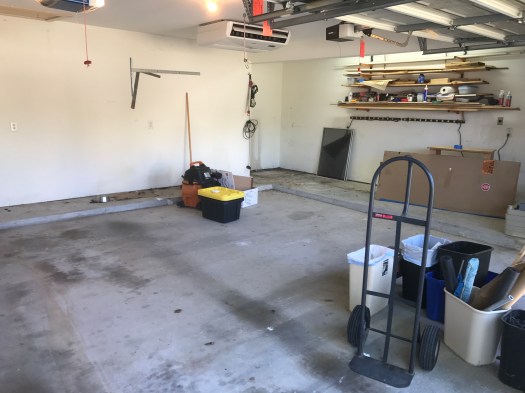
Here’s a picture of where I started, after significant removal of material. Nothing you see here remains as it was except for things attached to the ceiling.
Before
The experience at my employer’s production facility made it very clear to me that everything in this garage was going to be about one thing Light. I can attest after living here for 15 years before starting this project that the garage wasn’t a good workspace. Even with the lighting I had added, it was still dim in the workshop extension.
But I wasn’t happy with just taking a guess. I wanted to see what it would look like first. Having more time than money, I modified the floor and walls in my Fusion 360 model until I was happy with it.
So starting with the model from my last post, what you see is that the material I default to in Fusion 360 is 6061 Aluminum. Right. It’s shiny and gray colored. If you were to go render it you’d quickly discover that it reflects lots of light.
Let’s fix this by making the materials more realistic.
We’re going to use the F360 native material Limestone from the Stone folder in the Physical Material palette to represent concrete – there’s a ‘concrete’ in the appearance palette, but it’s tiled and doesn’t look right. Besides, we’re going to cover it up shortly anyway. The walls we’ll make out of paper in the “misc” folder in order to get a reasonable surface texture.
This should look approximately like my garage did when I started.
Model with wall material as ‘paper’ and floor as limestone
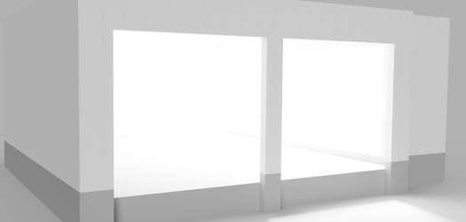
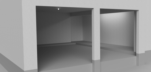
Let’s render this quickly so we can get a baseline look – with no ceiling – and get an idea what it will look like.
Baseline rendering
It doesn’t look bad, does it?
This is why you have to put in the ceiling… Things get a lot darker when you do that. So let’s use Sketch 2 from my previous post to create the ceiling since it includes the entire perimeter of the garage:
Back in the Model environment, turn on Sketch 2
So let’s select all the profiles and create a ceiling as a new body:
Ceiling extruded 12″ – note that it’s in aluminum by default
Since the ceiling is covered in drywall, let’s make it from paper as well (we’re not doing strength calculations here, just evaluating lighting and colors). Now re-rendering it we get a much different result:
Oops. Where did all the light go?
The renderer provides a strong light source that is blocked when you add the ceiling. So now we need to add at least some light to get a representative idea of what it will look like.
Let’s add some light sources. To date, I have a single LED light bulb in the middle of the ceiling and some daylight white fluorescents in the workshop extension.
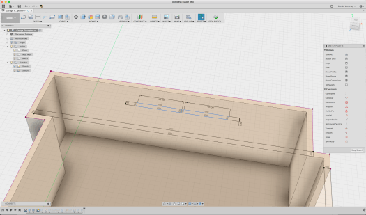
To make these lights, we turn off the ceiling and use Sketch 2 as a starting point, and create two rectangles 5×48″ long set end to end to create the fluorescents for the workshop extension:
Creating the fluorescent fixtures
Once the rectangles are laid out, extrude them about 2″:
Extruding the rectangles to create the fluorescents
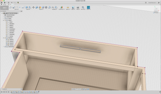
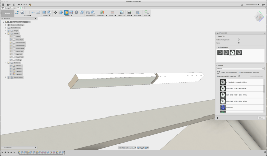
What we’re going to do now is to create a light source by using the LED emissive appearance. And since only three faces emit any light, we’ll just apply it to those faces.
Applying the emissive material to the surface of the ‘fluorescent’ fixture
Once applied to the bottom and longitudinal sides of the fixtures, we put back the ceiling and the wall (removed temporarily to get easy access) and re-render it:
This isn’t heaven, is it?
Obviously, I used the very brightest LED output to start with, so let’s make it closer to reality. A single fluorescent tube puts out between 50-67 lumens/watt, and the fluorescent tubes in these fixtures are 32 watts each. This means that a single fixture puts out 3200 lumens. The luminance value used by F360 is (essentially) lumens, so we can enter that directly.
Open the Appearance palette and double click the LED element used by the fluorescent fixture (it’s the bright white ring in the “in this design” box):
Editing the luminance of the emissive appearance
Now where you see the “luminance” edit box and change it from 48,000 cd to 3200 cd/m^2 and click “done”. Now re-render it:
That’s more like it… Except now it’s dark!
So now we’re pretty accurately modeling the lighting in the workshop space. Let’s add another light fixture in the middle in the fixture that the builder installed – this time a daylight-white LED bulb. We’ll just model this as a 2.5″ diameter sphere of 1500 lumens:
That little 100W equivalent light doesn’t do much, does it?
You’re right. It’s pretty dark. So I could add a LOT more lighting, but that’s a lot of work, and the concrete floor doesn’t help at all.
What are the options for a garage floor?
A vinyl floor would be hard wearing and resistant to liquids – don’t forget that a car will be put on this floor every day – so some sort of roll out tile floor isn’t out of the question. Here’s an example, Congoleum sheet vinyl flooring which costs $2.97/sq ft from Lowes:
Vinyl sheet
A ceramic tile floor would work too. But grout, oil, and radiator coolant are probably a bad combination. Cost for material is anywhere from $4/sq ft and up, and installation is labor intensive.
Plastic or rubber floor tile is an attractive option – it can be had in sheets or as individual lock-together tiles. Here’s an example, a white coin-pattern plastic tile for $3.79/sq ft, no adhesive required:
Rubber Tile
The good part with this stuff is that you can install it yourself and it’s easy to repair.
But think about it. You’re going to be moving some heavy stuff over this material – it needs to be very smooth and hard to be at all durable. Sure, it’s meant to be parked on, but how about running a pallet jack or an engine hoist over it? And I can tell you from experience that you’re going to get scratches and marks on it. A rubber tile can be replaced easily enough but it may make things more difficult when you are putting those heavy loads on it. (I thought for many years the right way to go was this sort of floor tile – it took quite a while for me to accept that this wasn’t the right option – and a 1200lb CNC mill…)
Epoxy coatings are an economical solution. It takes about 2 gallons to completely cover a 2-bay garage floor. And at about six cents per square foot for the material, it looks like a very inexpensive solution.
This is the approach I went with, but not the stuff you buy at Home Depot or Lowes. There’s more to it than just cleaning and degreasing the floor to get the stuff to stick. I started researching ways to treat the floor and concluded that there are two accepted ways to go about it: 1) apply an acid etch to rough up the surface so the epoxy will stick to it better; 2) use a mechanical method to rough up the surface. The acid struck me as a bit of a dicey proposition because it will eat away at the calcium in the concrete if it’s not thoroughly washed away, so the mechanical solution struck me as a better way to go, if one I wasn’t going to want to do myself.
So what color to use? The normal color people put in a garage is some form of gray with the notion that it hides dirt. It’s also typical to distribute multi-colored flecks over the surface before adding the top coat.
But that flies in the face of two things: increasing surface brightness with the available light and finding stuff you’ve dropped on the floor. (If there’s one thing I’m really good at it’s dropping small things and spending lots of time looking for them) Speckles and dropped fasteners or small parts tend to look very similar. Things are a lot easier to see if you’ve dropped them on a solid color, and in particular white. White shows more dirt, no two ways about it, but it also means you know when you need to get down there and clean it! (and it’s easy to do with a dust mop)
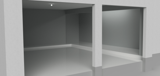
So how will this look? Let’s go back to the model. In the “appearance” palette, find the white gloss paint color, then apply it to the floor faces only.
Now it’s getting brighter
The available light now reflects off the floor and makes the whole space brighter. The real surface is not as smooth and will not be quite as reflective, but this is a good enough representation.
I hired a local epoxy floor contractor, Houston Epoxy Floors, to do the work. The price was about $2.50/sq foot and well worth it because they did a good job and stood behind their work. They used a diamond hone to rough up the surface and then filled any surface cracks before applying a two-part epoxy paint and then finally applying a clear polyurethane wear coat on top.
Putting down the base coat.Floor is basically done – but now the walls look bad
It takes two colorcoats to do a plain white floor. With gray and flakes you can do it in one. Plan to pay extra to get that service, since there aren’t flakes in the coat to hide the thin spots in the white paint. If you have exactly the wrong concrete it might take three. Work with the contractor to figure it out.
It wasn’t quite as obvious before that the walls were scarred and tired looking so the next task was to fix the wall color.
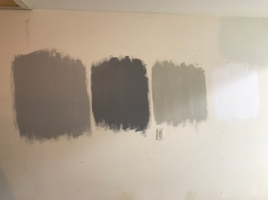
A trip to the Sherwin Williams web site followed by an in-person visit to one of their stores provided the information I needed – and three samples of paint. Since the floor is white, it seemed excessive to make the walls white as well – and they really would show every bit of dirt and wear.
I tried several samples of gray and a white color
The final solution was Monorail Silver. Serious Gray was too dark, and Useful Gray was too brown. High reflective white was there just for contrast.
Shades of gray (and white)
To put this in the render, I opened a screen capture of the color from S-W’s web site in Autodesk Graphic an used the eyedropper function in the color picker to sample the color:
Using the above process to grab the RGB values, I tried all the colors I had sampled on the model first. Using the rough powder coat appearance as a base color, I changed the color from ‘gray’ to the RGB values of the color I wanted to try. The render of the Monorail Silver (RGB 184,188,187) came out pretty well – and is similar to the final result:
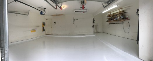
Because this is a garage, I bought Sherwin Williams best exterior latex semi-gloss paint and after patching many holes and scrapes in the drywall painted the walls. The end result took a few days, but came out fairly well:
Walls painted in Monorail Silver
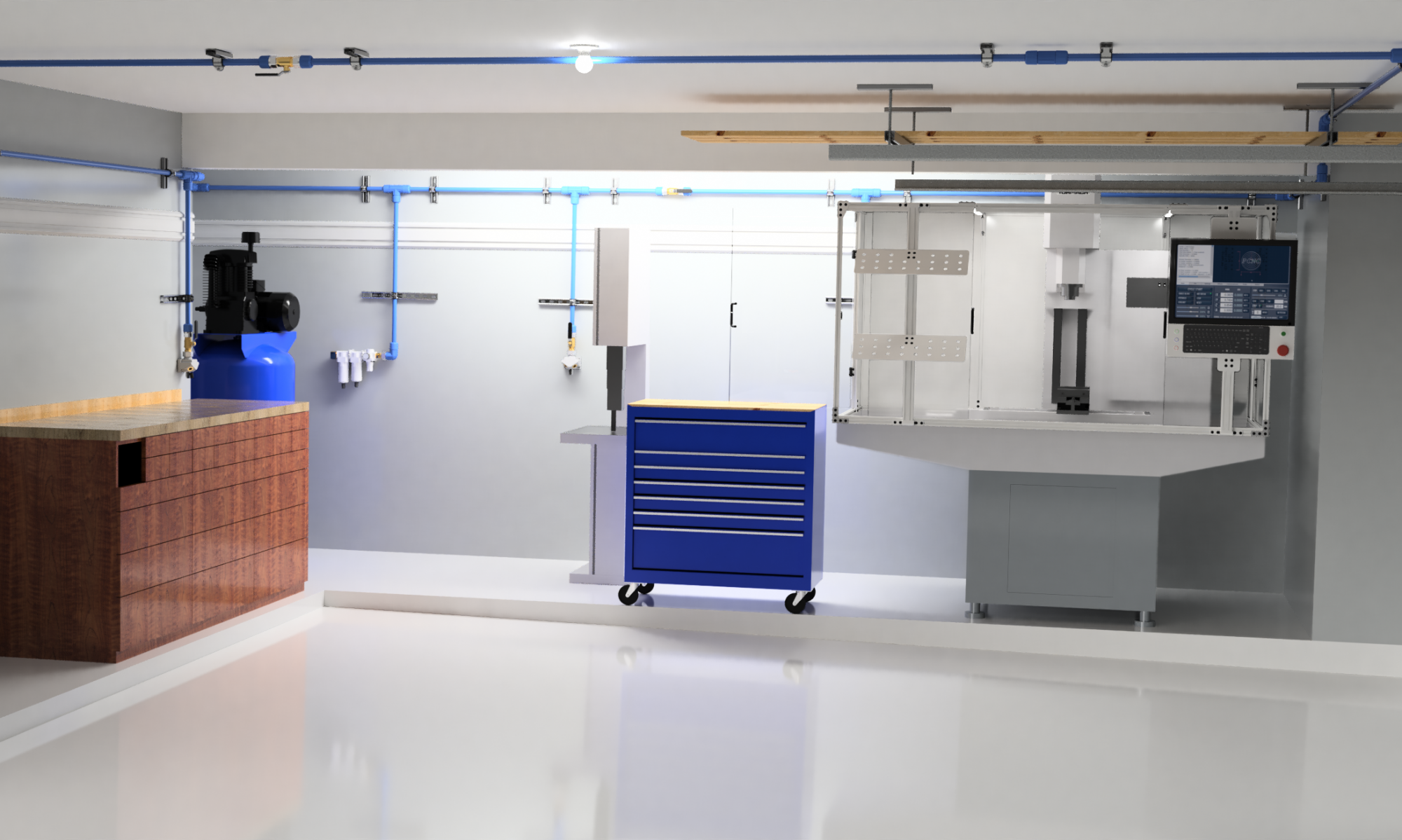
And you can see that the light reflects off the walls a little better than it does in the rendering – probably the semigloss paint (matte paint isn’t available in exterior colors). The picture below was taken in the process of installing the air distribution system – which we’ll get to in future posts. But you can see that the work spaces are well lit and the walls don’t stand out. It still needs more light, and of the right color, which will take some time because it requires me to get up in my 120ºF/95%RH attic to add more work boxes for additional light fixtures. Maybe in January…
There’s more to come, but next time we’ll talk about where to start putting things and how they actually ended up. Storage is the #1 problem in any garage, and there’s much not worked out yet. Note the wood and other stuff in the foreground above – that all had to find a home, and eventually did. It only moved about six feet… (Explaining that trick will probably require its own post, but it cost maybe $25 in materials and took an hour or so to do)
Have a great day, and thanks for reading!
UPDATE: Two days ago I added three 4ft 5000K 2-tube LED lights. There are dimmer operating rooms. Cost was fairly reasonable too in a 4-pack. I may add one more once I figure out how to mount it and hide the power cable.
A two car garage is not as big as you might think. Particularly if you intend to put two cars in it when you aren’t working in it. And if you live on the Texas Gulf Coast, it’s hot and humid in the summer and cold (and humid) in the winter with hardly any days when it’s actually comfortable. Add to this that you need good light if you want to do anything (this is still a work in progress for me).
Residential garages are not like bespoke shop buildings. They have low ceilings, garage doors (and door tracks) with short openings, steps, and things like attic accesses that need to be available, limiting the available floor space. And you simply do not have floor space if you want to keep a car in it.
Another problem is that your typical garage floor is made of very porous, dark gray concrete that does nothing better than absorbing everything that comes in contact with it, including light. (A gray hole?)
Solving all these problems is going to be dependent on your situation, but there are some common threads that my experience may be helpful with.
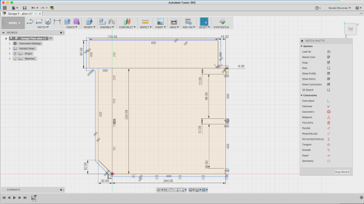
The place to start is the floor plan. Measure everything. Be accurate and pick up on details. Below is a floor plan based on my garage measurements (it’s not exact, since this is an example).
Floor plan with rough dimensions
While the picture above was created in Autodesk Graphic, the original sketch was made in Autodesk Fusion 360 with some slips of paper used to gather the dimensions to generate a 3D model. Primary tools to make these measurements were nothing more than a pen, paper, and a tape measure.
Keep in mind that you don’t need computer design programs to capture this floor plan. A pencil and a piece of graph paper will do quite well for 2D layout of the space.
Now if you’re looking at that floor plan and think that’s a lot of space, let me disabuse you of that notion. For this project, I set a couple ground rules:
There will always be room on the floor for two cars. If anything takes up space in a car bay it MUST have a place to go when not in use.
Nothing is stored on the floor unless it can be rolled away to use the space for something else (exceptions are anything that is too heavy to move or requires re-leveling after being moved)
Ground Rule 2 sounds like a challenge, but the fact is, if you don’t have space to work in, you don’t have a shop. You have instead a storage space that you happen to use for making things. By requiring that storage be movable, you preserve your effective floor space. If I have a project that needs the whole garage, all I have to do is move the car(s) outside and reorganize what remains to leave room for my project. For things that can’t move, they had better earn their keep.
How you choose to organize your shop is up to you. This series will attempt to follow some of the guidelines of the Kaizen/Lean manufacturing theory to make the best use of the limited space available. We’ll talk about Lean more later – but keep in mind that the goal here is to keep the clutter down and always be able to find things quickly.
Going back to the floor plan, you can see that there are some obstacles in the floor itself. The two car bays are on a slightly tilted slab (intentionally, so it drains) that sit from 4 to 6″ below the level of the house floor. This presented an enormous problem in working out where to put machine tools, i.e., the level areas are the only place to put them. (Since Ground Rule 1 says the car bays have to be open anyway, this is less of a hardship, but is part of the reason why the rule exists in the first place.)
The next problem is figuring out where everything has to go. Not including items needing storage (a much different problem), in my situation there had be places for the following:
80×30 Workbench/cabinet
PCNC 1100 Mill
80 gal stand compressor (there will be a post on this)
10″ Siding Compound Miter saw (on stand)
16″ woodworking bandsaw
floor standing drill press
floor standing scroll saw
It should be no surprise that over a year later, the bandsaw, drill press, and scroll saw are still not back in the garage… Not that there isn’t space, but as soon as they’re in place, there will be no room to maneuver. They all need to be made mobile, and that’s another project.
The real problem comes from trying to visualize each machine in the space. You can do it in 2D, like this:
Garage Floor Plan with initial equipment layout
This arrangement, which among other things violates Rule 1, makes poor use of the space available. Presumably the space along the left wall could be used for storage with shelving or cabinets.
The trouble is that most people will have a hard time visualizing how this will actually work. Where do materials come in? Where can things be stored? There’s no sense of vertical space, which turns out to be very useful in making space for everything. And what the heck do you do with that beam that runs across the opening to the garage extension?
So how to add another dimension? 3D CAD, of course, specifically Autodesk Fusion 360. For those of you not familiar with this tool, Fusion is an easy to use 3D CAD/CAM/Simulation environment that is offered free to hobbyists and low cost to business users making over $100K/yr.
So the way to begin is with a sketch. Once you have a copy installed on your computer, Open Fusion 360, and as soon as you have the window open, create a new project and save the file (this guarantees that F360 will keep a recent copy in the event your system crashes for some reason):
Creating a model of the garage in Fusion 360
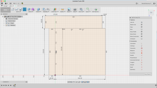
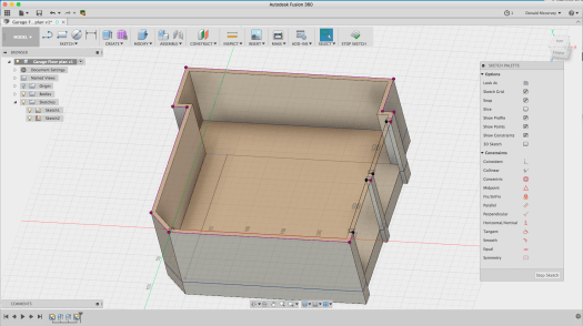
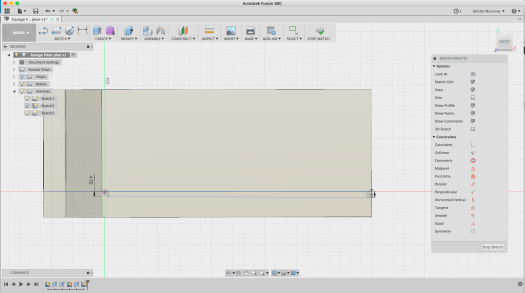
Now create a sketch on the XZ plane by clicking on the two-point rectangle on the ribbon, selecting the XZ plane on the workspace and laying out a rectangle for the car bays:
Create a sketch of the car bays
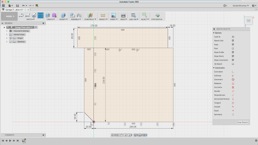
Add more rectangles for the other areas you measured – for this model the Workshop Extension and the raised step at the back of the garage.
Adding the outer work spaces
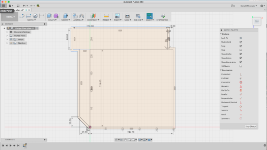
And if you go back to look at the original flat sketch, you’ll see that there are details for the garage doors, walls, and the diagonal doorway on the lower left. The latter is created by removing the Horizontal/vertical constraint, and then moving the corner 30″ upward to create the angled doorway:
Adding angled doorway
Creating the outer walls is done by selecting each wall segment and then using the “offset” command (under the “Sketch” menu) to create an outline that is 6″ thick. The offset requires that you break up the horizontal line between the top rectangle and the two lower ones so that the entire perimeter can be selected. Just select those lines, delete them, and then replace them one at a time using the Line command:
Deleted lines
In this case, you want to ensure you keep the line for the step between the car bay and the workshop extension
Replacing the lines
Now select all the line segments that make up the perimeter of the space and use the offset command to create the outside wall:
Offset outside perimeter to create a 6″ thick wall
The two garage doors are 96″ wide, and since we don’t need a super-accurate model of them, we just create rectangles in those spaces and delete the wall in those locations (you’ll find you need to patch up the lines for the outer wall – do this with the line tool):
Creating the garage door openings
At this point you can stop the sketch by clicking “Stop Sketch.” This is enough to create a solid model for the floor and the walls, which is all you really need for layout.
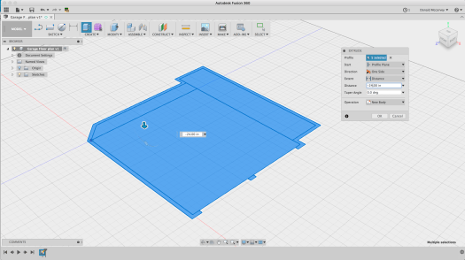
From here, we create the solid model by selecting the whole floor, then using the “extrude” command to create the foundation, which is arbitrarily made 24″ thick, going in the negative direction:
Extrude the floor to create the foundation
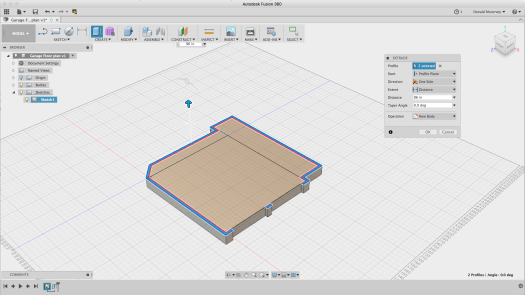
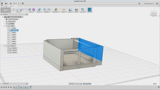
You’ll need to show the sketch again – so click the arrow next to the “Sketches” item and then click the light bulb button to turn the sketch back on. Select the walls and extrude them 8′ – but make sure to create a “new body” – you’ll want to be able to remove them from time to time to get a better view:
Extruding the walls – note that the center post has to be selected with a command-clickWalls extruded
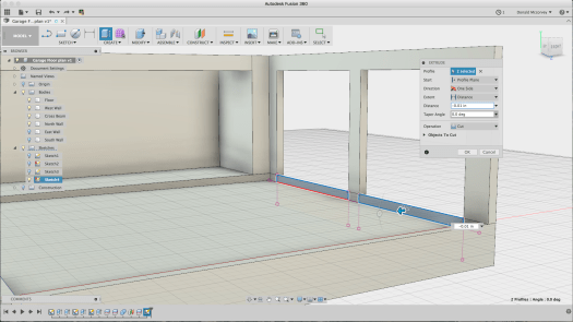
The garage door openings aren’t that tall – they’re only 7′ – so we need to create another sketch which will allow us to create the headers over the doors. We’re also going to create the sketch for the ceiling, though we won’t use it just yet. To quickly create the ceiling, use the “project” command and select each outside wall face, including the post between the garage doors. To create the profiles needed to make the header over the doors, you draw rectangles that touch the corners of the walls and the center post as you can see below.
New sketch to create the garage door headers
Before we create the headers, there’s a beam across the opening to the workshop extension which holds up the roof above. Since you should model all the constraints in your space, this is a good thing to include – and one of the reasons a 3D model is useful:
Creating the sketch of the cross-beam
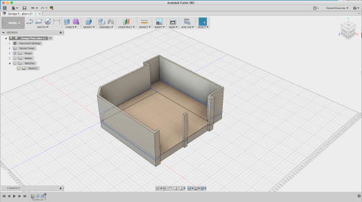
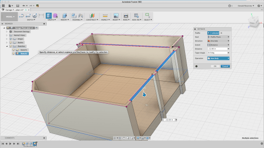
Now we can create the headers over the garage doors and the cross beam at once by extruding all three rectangles:
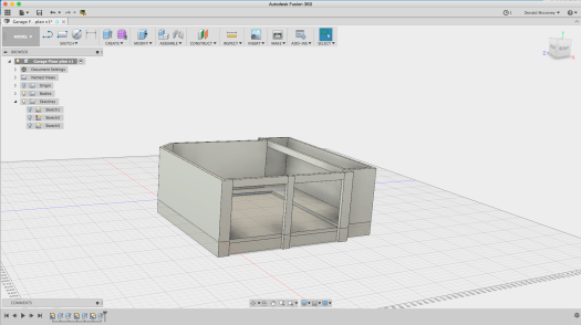
Extruding the Headers and cross-beamCrossbeam and Headers added
Note that these were created as a new body, not a join – this will change shortly.
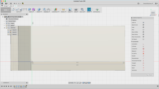
My garage has a challenge because of the sloped slab in the car bays. It’s 6″ below the floor level at the front, and 4″ at the back. To create this, we need another sketch, but this time, it’s going to be on the XY plane through the origin. You do this by selecting the XY plane when you’re prompted to choose a sketch plane. Since the wall is in the way, rather than selecting the wall face, hold down the mouse button over where the yellow XY plane is visible and a popup menu will allow you to choose any face or reference plane under the mouse cursor
Select XY reference plane from popup menu when you hold down the mouse button
Once you’ve created the sketch plane, draw a rectangle from the origin to the inside of the wall at the front by touching the line where it intersects with the sketch plane and then draw out a rectangle:
Draw a rectangle that goes from the origin (back corner of the floor) to the inside of the wall
Now, delete the horizontal constraint – the two parallel lines on the bottom line of the rectangle, then dimension the two ends to 4″ and 6″ as shown below:
Delete the Horizontal constraint, then set the dimensions of each end to 4″ and 6″ respectively to create the slope
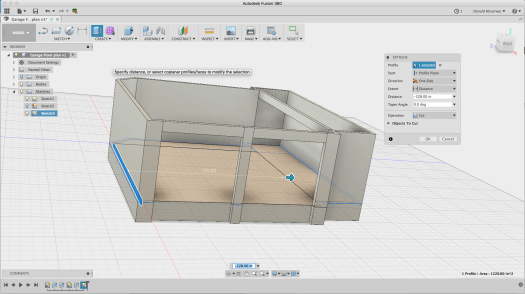
Now extrude the sketch profile 228″ to cut away the floor and create the sloped car bay:
Select the profile and extrude (cut) the profile across the car bays (228″)Hide the first sketch and this becomes the basic model
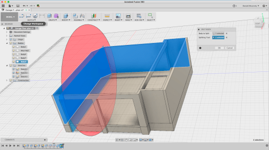
You’ll want to do a few more things to make the model work well. One of which is being able to remove walls when you want to. We’re going to split the model into four pieces: North Wall, South Wall, East Wall and West Wall, naming each of the bodies we create accordingly.
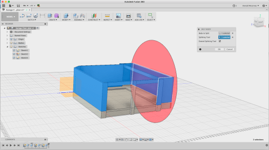
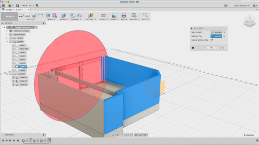
This is very easy to do, but perhaps not obvious. The west wall is simple: Go to the “Split body” tool under the “Modify” menu. Select the wall body, then select the inside of the west wall (that’s the one on the right side in all the pictures above) as the cutting tool:
Splitting the wall body, using the inside of the wall as the cutting plane
Now find and rename the body in the browser to “West Wall” to make it easier to identify:
Body 2 is the west wall – double click the name in the browser to edit and change it to “West Wall”
You’ll discover that most of the front wall is already cut from the rest, but let’s make it one whole unit. Use the same splitting tool to pick up the left side of the garage opening:
Splitting the edge of the front wall from the rest of the wall body
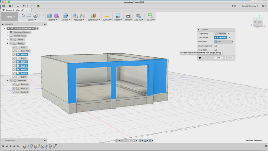
Then join the pieces that make up the front wall using the “Modify->Combine” command
Joining the front wall pieces together
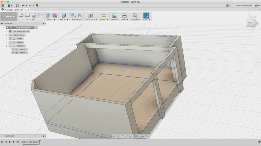
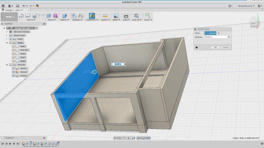
Finally, we need to split the east wall from the South wall. This is a little more difficult. Create a construction plane (Construct->Offset Plane) that is offset from the inner wall by 30″ so that it cuts at the edge of the doorway:
Create a construction plane to use as a cutting tool for the doorway section of the wall
Now use it to cut the wall body using the Split (Modify->Split) command:
Hide the construction plane, then finish the job by renaming all the bodies to their new names by selecting them to identify which body it is, then double clicking the name in the browser to edit and change them to East, South and North walls, respectively. Also identify the Floor and the Beam bodies.
Rename the bodies to make it easier to see them in the future
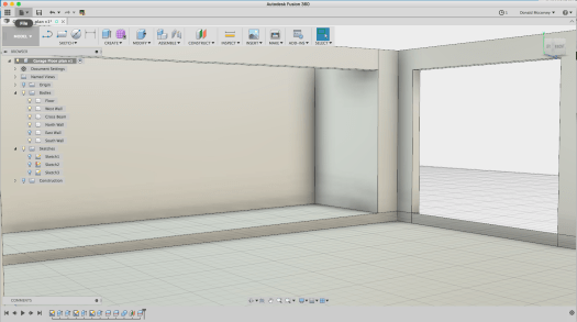
Now, you can rotate the model around and view it from various angles, removing walls as necessary to get an eye-height view of the space:
View from the doorway into the garage
Notice that there are some residual segments of the floor at the garage door opening. This can be removed by creating a sketch on that plane, using the “Project” command to create the profile and extruding it to cut it away:
Creating the sketch profile to delete the ‘flashing’ at the garage door opening
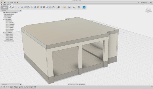
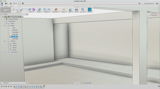
And here’s the finished product, looking from the left side of the left garage door opening:
Model with all walls and floors in place
You may be thinking: “What about the ceiling?”
Right now, lighting the model becomes a problem if you put in the ceiling and for the moment, you can live without it. Adding the ceiling becomes necessary later if you start hanging things from it and want to add lighting so you can get an idea how the space looks before you’ve spent any money on it.
For now, you can begin to see the available volume – and in some respects, how little there really is. Sure, the floor is open, but it’s usually filled with at least one car, and by Rule 1, there needs to be space for two. There’s a little unused space under the attic stair which we’ll add later, but that’s all the space there is.
Of course, you’re looking at plenty of other opportunities. If the floor is mostly off limits, then only those things that simply must reside on the floor are allowed to do so. Everything else has to be on the walls or hanging from the ceiling if it isn’t up in the attic (which is a limited space as well).
Ceiling space in particular is an underused resource. The space above a garage door, for example, is totally wasted, unless you have something somewhat long and flat that can be put there. The space above the compressor is similarly available (and not yet in use as of this writing – but it will be eventually).
Look at the space between the right garage door and the projection wall adjoining it in the floor plan. What might fit in that space? Bar clamps of many sizes will likely find a home there. A surveyor’s tripod is currently residing there and probably will continue to.
And consider what else you’re needing to reserve space for. For example, at multiple locations you’re likely to want a general-purpose air hose. You will not want that on the floor, so it needs to hang from somewhere. Punching holes in the walls for hooks means messing up the walls you probably just spent days patching up, so finding ways to use that wall space without dinging them up is worthwhile. (If you have a big budget, you might consider a slatwall system. With a more moderate budget, a partial slatwall will look better and be easier to keep clean than pegboard.)
Here’s another one that still isn’t solved: What to do with small parts? If you’ve been to the hardware store lately, all those screws and nuts and other fasteners add up quickly to a lot of cost. Throwing them out isn’t sensible, but storing them in a way that they can be usable is difficult. There are a number of ways for industrial storage of such parts, but they tend to be oversized and take up a lot of space (ACRO bins come to mind). Little chests of drawers are another answer, but they tend to become disorganized and are hard to see into. Another solution will get covered down the road a bit.
Lastly, consider cleaning this space in the future. My garage was built with drywall on the walls. With a fresh coat of paint, and the epoxy coated floor, it’s easy to clean if you can keep the clutter under control. It also means you have more light being reflected about and brightening the whole space. Dark, roughed-in walls are inexpensive, but they are hard to clean and easy to get filled with dirt and dust as well as other stuff that gets permanently stored there. So covering up those stud bays while not cheap, has some advantages.
Next time: Selecting and putting in a floor system
When this project started, my garage was crowded and hot, used mostly for storage, with a workbench and some makeshift shelves made from a lumber rack and a number of sturdy boards.
I’d show pictures, but I don’t find any in my collection that truly capture the total disaster area it was. And right off hand, when it’s 95°F and 100% humidity in late July, you really don’t care. It’s just a place where you drop things and get inside out of the summer heat.
But in the fall of 2015, I had an idea. The light fixture over the bar in my kitchen was put there by the contractor and was basically junk I had been looking for something better since I bought the house. Then Amazon had light fixture on sale for a ridiculously low price that had the shape I wanted, never mind that it was wired for a fluorescent bulb (which is why they were clearing them out). Three of them together and rewired for LED bulbs would put out a lot of light and really solve the lighting problems in my kitchen.
It took a while to figure out how to make it work, but eventually I concluded I needed three cover plates made of copper with a brown patina with some precisely drilled holes and one large 1″ hole that would need to be drilled to better tolerances than my drill press would ever be able to achieve.
I’ll put up a post on the light fixture eventually, but it was three simple 4x6x1/8″ copper plates that spawned what may someday turn into a little business.
How do I do this?
So how to make those copper plates? Well the first place to go is the Internet and start learning about CNC machines.
There are all sorts of small CNC machines out there that would have done the job. Nothing against them. They fit a particular niche and so long as you aren’t working with metals, there’s not much you can’t do with them.
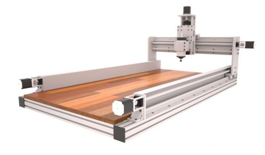
CNC Router
But my projects are mostly going to be in metal. Yes, you can do aluminum on a CNC router, and I can easily see using one for big, flat jobs (which I have some of in my list of ideas). But they lack rigidity needed to plow through metals without burning up or breaking expensive cutting tools.
I started looking at CNC mills. Phew! Those things get expensive. The *smallest* mill from Haas would just barely fit in my garage and started at $32K. A Brother Speedio might fit, but it was more like $90K. Used examples could be had for closer to $20K, but then you’re dealing with a machine that’s over ten years old and who knows how much work it needs to make it work accurately.
Photo: Haas
Haas Mini Mill
There are a number of “R45” Chinese Bench Mill conversions out there. These are small, relatively low horsepower machines with good, but limited rigidity. And they’re relatively cheap. you can start with a machine imported by Grizzly and convert it to run CNC using Mach 3 software running on a PC.
Photo: Grizzly Industrial
Grizzly G7055 Mill/Drill
And if you want to builda CNC machine as a hobby, that’s a great way to go. It may never make a product for you, however, so it’s worth thinking hard before you take this route. Not to dissuade anyone who wants to try it.
You won’t get much more than 1-2hp in a Chinese bench mill. You can put a bigger motor in it, but the accuracy will be limited. Cast iron seems heavy and strong, but when you’re trying to machine something to 0.0001″, these machines won’t get there with much more than 1.5HP.
If you want more horsepower, you need more cast iron. And that means the bigger, more expensive machines. (that was why the Haas Minimill was attractive – more cast iron, 15HP motor, but the cost was well beyond my means)
There’s another problem, of course. Electrical power in a residential home is pretty much single phase AC, 240V phase-to-phase (120V phase to neutral). Up to three horsepower you can get single phase motors pretty easily. And you can only pull down so much current from your service panel. Most residential homes are going to be 75-100A service, so when the air conditioning is running, and your shop compressor is on, and the mill spindle is going, you do not want the lights to go out as the main breaker on your house trips.
Intermittent loads are generally OK, so do a little math and figure out how much current you’re going to be pulling at any given moment. If it looks like you’re going over the available service, particularly as motors start up, you may need to upgrade your service (or buy another house or shop that has a bigger panel and possibly three phase power).
So when it comes right down to it, what you need is a machine that will work not just for the parts you want to make, but within the limitations of space, power, and cost. And that depends entirely upon what you want to do, where you’re putting your shop, and how much you have to invest in equipment.
There are a couple manufacturers who have decided to fill this niche. Tormach is one of them. They carry a line of three bench mills – the PCNC 1100 (1.5HP), PCNC 770 (1HP) and PCNC 440 (3/4HP). The 440 is the most basic, but can be had with a Power Drawbar (more on this later) and soon an Automatic Tool Changer (ATC). The 770 has a larger work envelope and more powerful spindle, but its primary benefit comes to users who want to move the machine to a basement shop since it can be relatively easily disassembled and carried down a set of stairs. The PCNC 1100 is their flagship machine and offers their largest work envelope and most powerful motor.
The fact is, the only difference between these machines in terms of their end product is how large their work envelope is and how fast they remove material.
If you can fit your project on the table in a 440, the 440 will do the job. My very first experience with a Tormach was on a 440 and while the machine is small it works remarkably well. It even has some advantages on the 1100 because of its 10K RPM max spindle speed for things like engraving. (The 770 also has a 10K spindle) The 1100 is limited to 5100 RPM (there is an optional high speed spindle).
The real advantage of the Tormach product line is their control software, PathPilot. Mach 3 works, but it hasn’t been improved upon in a while and is hosted in MS Windows. PathPilot is built on top of LinuxCNC which runs on a real time Linux kernel and so does not run into problems with operating system calls interfering with driving the stepper motors on the table and the Z-axis.
Pathpilot is easy to use and can be navigated with a touch screen monitor. It is network aware so with an inexpensive USB wifi dongle you can put the mill on your home network and move data to it as if it were any other networked drive – something that will be of more importance when you want to transfer your CAM programs to it.
The user interface is about as intuitive as you can ask for and works well with a touchscreen display, potentially eliminating the need for a mouse.
This isn’t an ad for Tormach, though it probably looks like one. It’s not without reason. Tormach is growing rapidly because they make a good product and sell it at an attractive price. Is it the best machine on the market? That’s up to the person buying the machine. For my particular application it should work well for quite a while.
One thing to keep in mind. Who you are is probably as important as what you want to do. I am an electrical engineer, not a machinist. This means practically that I am learning everything from the ground up. Bits and electrons I know. End mills and fly cutters are a new concept. My purpose is to teach myself a new skill while pursuing some personal projects and maybe build a business around it.
Make sure you are working around what you like doing, because if you don’t, you’re buying an awfully expensive paperweight.
Selecting a Mill
For the moment, let’s just talk about volume and cost. You have only so much space available in your shop and you have (presumably) a limited budget.
Sticking with Tormach, it’s really a more a question of how much you can afford and how much space you have to work in. The bare 440 mill will set you back around $5K, and fits in about the same space as a woodworking radial arm saw. (you can get the fully tricked out mill with stand, enclosure and some basic HSS tools for about $10K)
The 770 costs about $7K for the bare machine, and with the full stand and enclosure is about 50% larger than the 440.
The 1100 bare mill is a little over $8K and has a 42×80″ footprint when you add the stand and coolant tub.
Another thing to keep in mind is that you need space to get around the mill – make it wide enough for you to slither behind it to maintain and modify the machine. This is easy with the 440 – you could mount that machine on casters if you wanted to.
I went with the 1100 because I planned from the outset to make the room for it, and wanted to be able to maximize what I could make with the machine, though I was sorely tempted by the 440’s compact size and relatively low cost.
So with that decision made, the next problem was “where does it go?” in my crowded garage.


 Photos: Tormach
 Photo: Tormach